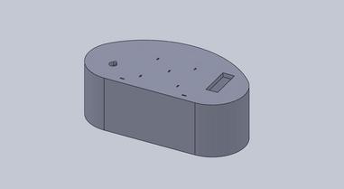
Initial Design Ideas
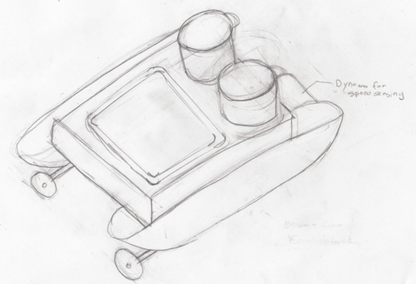
We decided to go with a catamaran design fairly early on for a few reasons: simplicity, maneuverability, and stability. Below is a very early concept sketch:
Our early concept involved using differentially driven propellers, with a dynamo driven by a paddle wheel for speed sensing (and closed loop speed control). We wanted to have a fan driven display of team color, as shown above, but we ran into lots of problems during early testing.
Initially, we went through a few controller ideas - steering wheel and sword w/ ultrasonic sensor were the frontrunners. However, we randomly got the idea of using a bike to control our boat, and immediately got hooked on the idea.
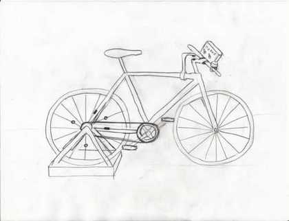
For the preliminary design review, the boat design was the same, and our bike design looked like:
The bike's rear wheel would be fixed to a stationary trainer. We planned on using two Reed sensors on the rear wheel to calculate speed/direction. We mounted a fixed gear so that the bike could be pedaled forward and reverse.
For the heading, we wanted to avoid contact sensing (for robustness), so some early ideas were: grayscale detection with tape sensors, compass, optical angular encoder, ultrasonic sensor with spiral mount. The compass seemed like the easiest option, but all the ones we found online (with simple interfaces) were over $50. Instead, we ended up finding a rotary Hall effect sensor online with analog output for under $20, which fit our needs perfectly.
For our third user input, we leaned toward using a bike bell. This could be integrated with a push button, microphone, or force sensor to quickly rotate, spray water, or blow bubbles.
For micro-processing, we chose to use an E128 on the bike for ease of debugging.
On the boat, we were required to have at least two microprocessors - with one coded in Assembly. To reduce the number of PICs we had to use, we looked for a PIC with two UART modules (XBee, Security Controller), 2+ PWM (for our propellers), and <= 40 pins (since we wrongly thought we had to use the PICSTART for programming). We couldn't find any 16 series PICs with those specs, so instead we bought a PIC16F777, which had everything we needed except for two UART modules.
Design Evolution
Although our primary design didn't change much after the preliminary design review, we did make some significant changes as we went along.
To make our lives easier, we decided to use a servo with flags mounted to display our team color.
After some initial testing, we found that using two Hall effect sensors to sense bike wheel speed/direction had a flaw. Our direction algorithm was simple - if we hit the same sensor twice in a row, we've changed direction. We assumed that we always overshot a sensor and then switched direction. In reality, if we switched direction without fully passing a sensor's high time region, we would not hit the same sensor twice in a row. This actually happened frequently, causing us to miss direction switches.
Since this was impossible to fix in software, we had to change our design and add another Hall effect sensor. With three sensors, direction could be detected easily by examining the current and last sensor hits.
After using the rotary Hall effect sensor on the bike, we realized we could use it on the boat to sense water speed and direction. Attaching the sensor next to the paddle wheel gives us an analog voltage that could be sampled and converted to a rotational speed/direction.
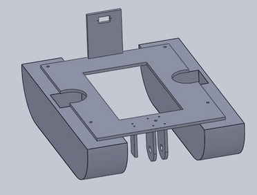
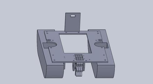
Once we decided on all the I/O for the boat, we made a preliminary CAD design of the boat:
The key features of our design were:
- Servo mounting block for team color display
- Supports for paddle wheel to measure boat speed and a side mount for a magnetic sensor
- Internal structural supports to add rigidity to our foam
- Acrylic top plate to secure components
The dashboard included room for a servo (left) to indicate boost recharging, holes for atoll capture LEDs, and a hole for the bike bell.
Final Design
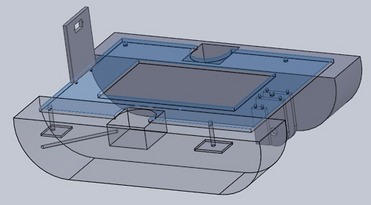
Below is the final version of our boat. We made only a few modifications to the original CAD model:
- Made a hole for the paddle wheel so that we could fit 2" paddles and have the rotation shaft out of the water.
- Added access holes for putting in and taking out motors.
- Moved the tupperware opening further back to make room for a paddle wheel.
- Added holes so that we could insert bolts to support a steel wire canopy.
