Mechanical Design: Summary
Our project was split in two separate sub-systems, the CVC (controller) and ACV (boat). Each system was outfitted with a ZigBee wireless radio for communication according to the protocol developed by the class.
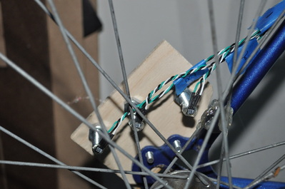
For the controller, we instrumented a fixed gear bicycle to get speed and steering commands. To measure rear wheel speed, we mounted three magnets around the spokes and attached three hall-effect sensors to the bike frame. Using interrupt-based input captures, we determined the rotational velocity and mapped it to a 0-100 PWM duty cycle. From the same data, we determined the rotation direction based on the order the sensors are triggered. We found the direction of the handlebars using a rotary position IC containing multi-axis hall effect sensors. For our third input, the driver rang a bell (with a push button mounted inside) to initiate a boost.
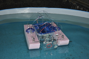
We built a catamaran style boat with a dual propeller propulsion system. Our goal was to maximize the boat’s stability by evenly distributing the weight and keeping a low center of mass. Using a differential drive strategy allowed the boat to move forwards, backwards, and change direction depending on the bike’s commands. To improve the boat’s response we added a paddle wheel to measure the boat speed, which gave us the opportunity to implement a control loop. To protect the electronics from water, we used a wire frame covered with clear plastic as well as Tupperware containers for each sub part.
Mechanical Design: Bike
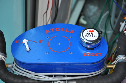
All the electronics for the controller were housed in a small container between the handlebars. On the top face, we attached a modified bell containing a push button to trigger the boost. Also, there is a five LED display that shows what team has control of each atoll. Lastly, a servo changes position as the boost recharges.
We rigidly attached three hall-effect sensors to the bike frame via bolts. Three magnets were equally spaced on the spokes so there will be a regularly generated pulse.
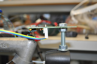
The Melexis rotary sensor was rigidly attached to the bike frame adjacent to two magnets on the handlebars. This allows us to determine the rotation of the handlebars relative to the bike.
Mechanical Design: Boat
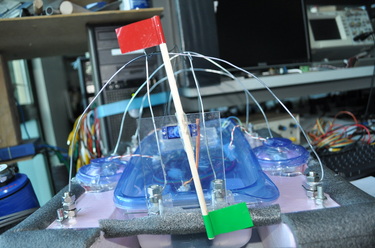
The team color flag (red or green) is lifted by a servo mounted at the stern.
The first layer of water protection consists of a bent wire frame, covered by a clear plastic sheet, and attached to our main support plate using nuts and bolts.
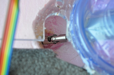
Each half of the propulsion system consists of a propeller mounted to a 1/8" diameter shaft, which is connected to a H615-66430 motor using a u-joint coupling. The shaft is contained sleeve filled with Renolit ST-80 lubricant, which prevents water from moving up the shaft. Both motors were secured inside Tupperware containers with tightly fitting foam blocks.
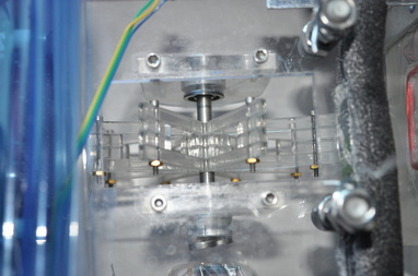
We built a paddle wheel out of acrylic and attached it to the bow with ¼ inch roller bearings press fit into vertical acrylic supports. A Melexis rotary sensor was mounted adjacent to two magnets on the shaft allowing us to measure rotational velocity of the paddle wheel.
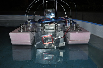
The RFID antenna was attached to the bow with an L-bracket making it easy to steer the it towards the atolls for capture.
CAD
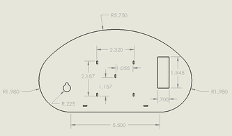
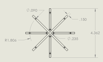
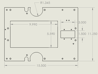
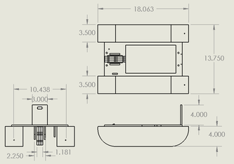
Detailed drawings are shown below for the main parts of our CVC and ACV
